The technology

Sound has a
shape.

Every leak makes a noise. Most of it above what the human ear can hear. Acoustic imaging turns that noise into a picture, so a leak that's invisible and inaudible on the factory floor becomes a coloured hotspot on a screen.

Acoustic imaging

An array of microphones, not one

The imager LeakHawk uses carries dozens of ultrasonic-sensitive microphones arranged in an array, paired with a normal camera. Rather than pointing at one joint at a time, it scans a whole area at once (walls of pipework, overhead lines, entire machine cells) from several metres away.

Step 1

Listen across the spectrum

The array picks up both audible and ultrasonic sound, well beyond what a person can hear, across a wide frequency range. Leaks generate a distinctive high-frequency hiss that stands out from normal background plant noise once isolated.

Step 2

Map the sound to the image

The imager calculates where each sound is coming from and overlays a colour map directly onto the live camera image, so the leak isn't just detected, it's visually pinpointed on the actual pipe, fitting, or joint.

Step 3

Quantify, not just locate

Using the measured sound level and the distance to the source, the imager estimates the size of the leak, the same estimate that feeds directly into the dollar-cost figure in your report.

Step 4

No shutdown required

Because it works from a distance and filters for the leak's frequency signature, scanning happens while the line is running at full production: no isolating equipment, no lost output for the inspection itself.

See it in action

Watch the imager find a leak

Fluke's own demonstration of the ii900 acoustic imager, the same tool LeakHawk uses on site, turning a leak that's completely silent to the ear into a coloured hotspot in real time.

How leaks get found today

Every other method makes you choose

Between knowing how much air you're losing and knowing where it's going. Between finding leaks and keeping the line running. Here's what's actually in use on Australian sites, and where each one runs out of road.

Soap solution

One fitting at a time

Still standard practice, and it genuinely works on a joint you can reach and already suspect. But it tests one connection at a time, tells you nothing about leak size, and anything sprayed on overhead pipework ends up on the floor as a slip hazard.

Walking and listening

Above the range of hearing

Escaping air creates turbulence that radiates strongest well above 20 kHz, commonly around the 40 kHz mark. Human hearing tops out near 20 kHz, so the loudest part of the leak is silent to you. What's left in the audible band gets buried under compressors, conveyors and plant noise.

Handheld ultrasonic detector

Slow, close-range, ladder work

The long-standing industry go-to and a capable tool. But it's a single-point instrument: you sweep an area, then narrow in with a focusing probe, one zone at a time. You need to get close, which means ladders, EWPs and crawling behind machinery. Industry guidance treats these as reliable for locating leaks and unreliable for sizing them.

Pressure decay test

Requires a shutdown

Isolate a receiver or branch, close every outlet, and watch pressure fall over 15–60 minutes. It gives a defensible total for that section, but only during downtime, and only if nothing is passing internally. One undocumented valve or a live actuator invalidates the result. It also tells you a section leaks, never which fitting.

Flow metering

How much, never where

The strongest way to establish a whole-plant baseline and prove before-and-after savings, especially with clamp-on meters that don't require cutting pipe. But a meter is a measurement device, not a search tool. It will tell you the plant is losing 90 SCFM and leave you to find it.

Thermal imaging

Only the big ones

Sometimes offered alongside energy audits. Research comparing the two methods puts thermography's useful range at larger orifices (roughly 1 mm and up), and it depends on a temperature difference being present. Most of a plant's leak count sits well below that threshold.

None of these are bad tools. The problem is that no single one of them answers both questions a maintenance manager actually has: what is this costing me, and which fitting do I send someone to, without either stopping production or spending days on a ladder.

Under the hood

What the report is built on

Every figure in your LeakHawk report traces back to a real, on-site acoustic measurement, not a desk estimate. Audits are scoped and run against ISO 11011 leak survey guidance, and we're fully insured with standard site inductions handled before we arrive.

Effective scan distance~1–8m ideal, useful line-of-sight to ~21m
Sound range detectedAudible through ultrasonic (well above 20 kHz)
OutputColour sound-map overlaid on a live photo
Leak sizing basisMeasured sound level + distance to source
Production impactNone: scanned live, no isolation needed

These are engineering estimates, not lab-grade flow measurements. Every acoustic method produces estimates, including the handheld detectors. What matters is that they're consistent, repeatable, and based on your actual site conditions rather than a generic industry average. That's the number your repair-vs-leave decision gets made on.

See it for yourself

What you actually get

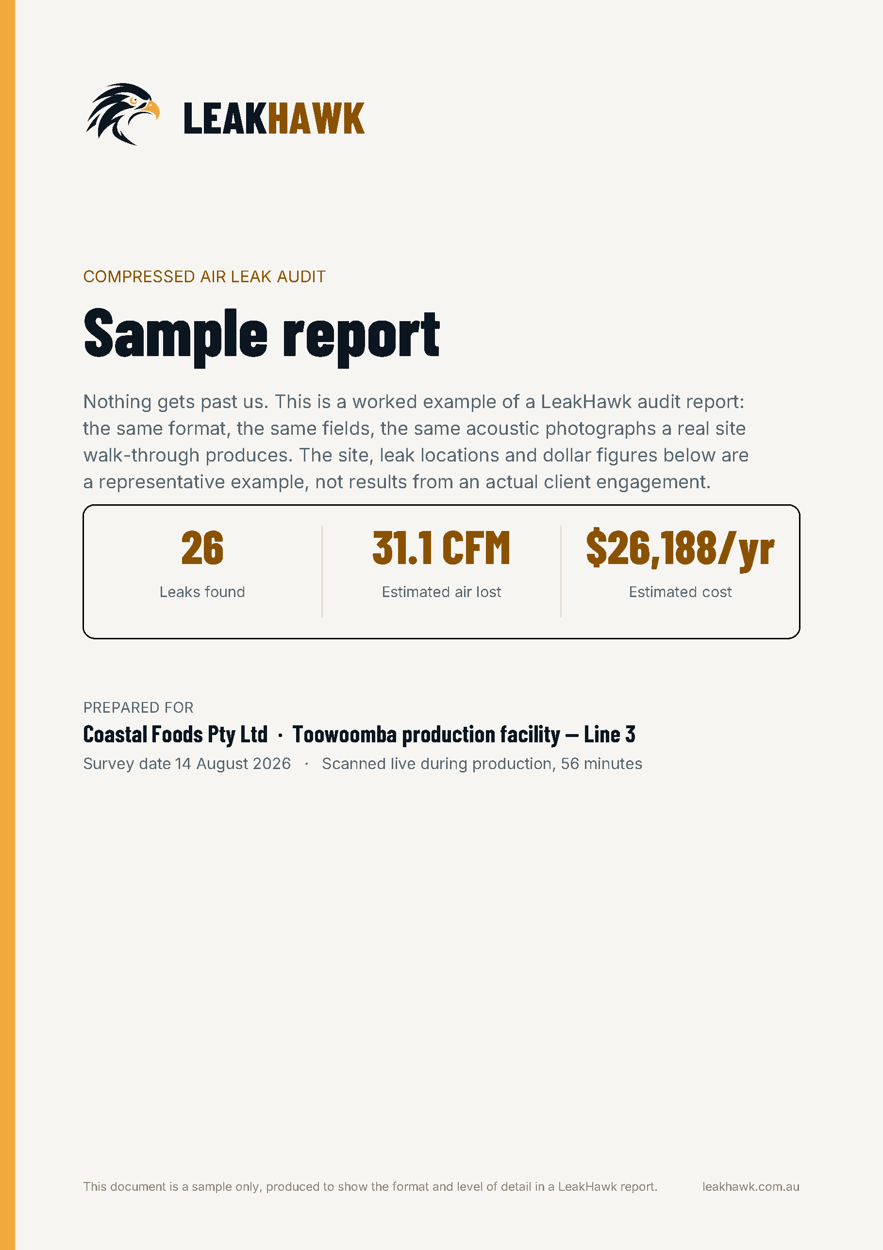
One audit produces one report: every leak logged, photographed and priced. Below is a full sample built to the same format your site's report will follow, so you know exactly what you're paying for before you book anything.

Cover page of a sample LeakHawk compressed air leak audit report

Sample report: 26 leaks, one production line

  • Survey summary: equipment used, system pressure, operating hours and the assumptions behind every dollar figure
  • Every leak ranked by estimated annual cost, not just listed in the order it was found
  • A full-page acoustic photograph for each leak, the same colour sound-map overlay the imager captures live on site
  • Leak type, distance to source, and estimated flow in both L/min and CFM
  • A repair priority on every leak, so your team knows what to fix first

The site, leak locations and figures shown are a representative example, not results from an actual client engagement.

Download the sample report (PDF)
Questions

What people ask about the technology

How does an acoustic imager actually find a leak?

It listens across an array of microphones rather than one, and calculates where each sound is coming from. The Fluke ii900 we use carries 64 microphones for this, which is what lets it overlay a colour map onto a live camera image and pinpoint the actual fitting or joint a leak is coming from, not just the general area.

Why does the number of microphones matter?

More microphones give finer spatial resolution, the difference between knowing a leak is somewhere on a wall of pipework and knowing which fitting it is. A 64-microphone array is also what lets the imager work from several metres away, rather than needing a single sensor pointed directly at a suspected joint.

What frequency range does the imager detect?

2 kHz to 52 kHz. Human hearing tops out around 20 kHz, so most of that range, including where a compressed air leak's turbulence is loudest, is inaudible to begin with. That gap is the entire reason acoustic imaging finds leaks a walk-through never will.

How accurate is the CFM figure in a leak report?

It's a genuine engineering estimate, not a lab measurement. The imaging software converts the sound level it picks up into an estimated flow rate using a model built from measuring a large number of real leaks at different flow rates and pressures. There's no fixed formula that turns sound directly into flow, and actual flow through a leak also varies over time with system pressure and whatever else is drawing air on the same line. What the estimate is reliable for is consistent, repeatable prioritisation across every leak found on a site.

What are the limitations of acoustic leak detection?

It needs reasonable line of sight to the source. Ideal working distance is roughly 1 to 8 metres, with useful detection extending to about 21 metres given a clear view. Strong wind and background noise reduce accuracy, since the imager is filtering for a specific sound signature and wind adds noise across those same frequencies. And like every acoustic method, it estimates leak size from sound rather than physically measuring flow.

How is this different from thermal imaging?

Thermal imaging looks for a temperature difference and only reliably picks up larger orifices, roughly 1 mm and up. Acoustic imaging listens for the turbulence a leak generates regardless of temperature, which is why it catches the small leaks, the ones under a millimetre, that make up most of a typical site's leak count.

Does it work outdoors?

Yes, but indoor, production-hours conditions are where it performs best. Wind and ambient outdoor noise sit across the same frequency bands the imager is listening on, which reduces accuracy compared with a sheltered indoor line. Most compressed air distribution worth auditing is indoors anyway.

Can it find anything other than compressed air leaks?

The imager itself can also pick up gas and vacuum leaks, but LeakHawk's audits are scoped to compressed air. We don't run partial discharge or mechanical/bearing diagnostics. That's a different tool, the Fluke ii910, which we don't use.